What's new

Replacing the 510 on the Cuboid

Joined
Aug 31, 2016
Messages
6
Hi Guys,
So this is the situation. I own a Joyetech Cuboid box mod which has a very bad 510.
By bad 510, i don't mean that i get the ''atomizer short or no atomizer'' message.
The issues i am having are:
- Reads all my atomizers higher than any other mod i own. (a 0.45 on other mods would be around 0.60 on the cuboid)
- Messy temp control as it keeps asking for the new/same coil all the time.
- I have to keep adjusting temp to keep up with the bad readings
As i really like the chip and its features, i would like to change the 510 to an aftermarket one. I believe this would increase the quality of this mod in a decisive way.
I took the Cuboid apart and noticed that the space is very limited.
Anyone has any suggestions on the 510 i could/should use or the process in general?
Do you think this is worth it?
Thank you...
 
I've been trying to squeeze a fat daddy 510 v4 into mine all afternoon, same reasons.

It's not going well, I'm almost at the "sod this" point where I pop down to Maplin and just buy a box to put it all in.
I've had to cut away a lot of the top piece/heatsink, but now components on the board are clashing with the big brass nut that holds the 510 on, I'll grind it down a bit more to see if i can create enough space, but if not, well, Maplin is open till 8 :)

I realised, the entire negaitve circuit on this mod relies on pressed pins, the outer of the original 510 is press fit to the heatsink, and the negative battery point is also press fit into the heatsink, nothing else connects the neg to the mod.
I got a steady 0.3 ohms between those two points. The neg connection to the board relies on two screws into the heatsink too, guess what, lots of resistance there as well. If the chip takes account of this resistance I'll be shocked, I'm pretty sure it's due to poor connections.

If anyone else has carried this operation out and has pictures, please please post them.
Hi linus,
Thanks for sharing your experience.
I am also considering putting everything in a different box, as i think its gonna be a tough one replacing the 510 on this box.
That would also eliminate the other defect of the Cuboid which in m opinion is the battery door.
Truth is, putting everything in a different box would be a bit of a challenge for me, as i never built a mod before.
Any tips on doing that?
 
Truth is, putting everything in a different box would be a bit of a challenge for me, as i never built a mod before.
Any tips on doing that?

I'm still thinking it through, I guess getting a different battery sled might make life easier, or I'm going to have to cobble together a solution with the parts from the original box, however, the top pins on the battery connector are spring loaded, and the bottom connector is just a single piece, so I don't think it would be too hard to fashion them into a frame that can have batteries inserted and removed from the side. It's important to remember that the door end of the battery box (i.e. where the positive of the first battery connects to the neg of the second) has to also connect to the board for the balance charge and battery voltage measurements. That's what the little spring loaded pin under the battery door is for, so, easy enough to just hard wire to that point on the board if using a battery sled.

The other problems to solve, cutting the box for the display and buttons, easy enough if you use the original screen cover as a template and just drill out the holes then file them nice and tidy, could even use the screen cover to neaten it up. Fire button might be a challenge, but I may just wire in a new push button switch for that. Finally, fixing it in, and fitting it in. Hot glue for the most part, easy to use, and easy to remove if it goes wrong (nail polish remover just makes it let go). :)
Because of the width of the PCB the standard layout I see in most DNA devices isn't going to work, batteries are going to have to stack at the back with PCB underneath (front of the box) but I don't think that is much of a big deal.

As I said, these are just my initial thoughts, plans always change during the execution for me (i'm a bit "do, think, do"), this would be my first serious vape mod modification.


I'm going to give the heatsink another go first, as I had chipped paint on the mod and I found an odd, unevenly striped, copper and silver surface under the paint. I think I can make it look really nice and original, so i don't want to abandon it.
I may just dremel away the problem parts of the retaining nut until it all slots back together, that may work.
Thanks for your reply man.
I have an evic VT with a broken chip sitting along, and at least visually the 510 looks the same.
I will try to use that in the Cuboid but if that doesn't work its gonna have to be a new box....
Keep us posted on the progress!
Thanks again!
 
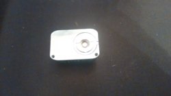
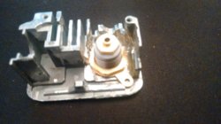
Well, it's a bit ugly on the inside, but after much dremel, I got the 510 to fit, I haven't soldered anything up yet but it looks workable.
Circuit board clearance is tight so I may knock up an insulator from some 0.25mm plasticard, just for safety.
Now the only issue is the 510 is proud of the top of the mod by about 1mm. I have a 22mm 510 which just covers the recess but I don't have tools that will let me deepen the recess enough for a flush fit. I may have to see if I can get a low profile 510 to fit properly.

So, yes I think it's feasible, but man this was a messy job. If I had milling equipment it would have been pretty straightforward, but if I could afford milling equipment I wouldn't be spending a day trying to rescue a £35 mod, I'd be making my own.
I'm thinking a rebox might be the better/easier option.

2016-09-16 09.54.05.jpg
2016-09-16 09.54.24.jpg

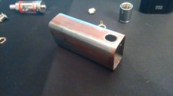
And the box I want to rescue
2016-09-16 09.55.26.jpg
 

Attachments

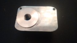
  • 2016-09-16 09.54.49.jpg
    2016-09-16 09.54.49.jpg
    1.6 MB · Views: 89
Last edited:
Grrrrr...
Last minute frustration, there's no clearance for the positive pin, it clashes with the back of the battery housing when it's all nipped back together. They do a short throw one, but I'm going box shopping, had enough. Don't personally recommend this approach :(
 
Grrrrr...
Last minute frustration, there's no clearance for the positive pin, it clashes with the back of the battery housing when it's all nipped back together. They do a short throw one, but I'm going box shopping, had enough. Don't personally recommend this approach :(
Hi,
I have too decided to go for a box. Want to get rid of the battery door of the original box as well.
Will purchase the box in the next days and post my adventure here...
Thanks again for the post.
 
Back
Top Bottom