You are using an out of date browser. It may not display this or other websites correctly.
You should upgrade or use an alternative browser.
You should upgrade or use an alternative browser.
how to wire an illuminated fire button on an sx350
- Thread starter 1000moths
- Start date
Jasen
Postman
- Joined
- May 31, 2014
- Messages
- 129
Was discussing something similar on another site.
You need an N fet like this one Infineon BSR802N L6327
Copy/paste from CraigHB
<It's not a complicated task to switch power to the battery monitor, just use a small power MOSFET in an SOT23 package which is not terribly small or hard to work with. The MOSFET gate is driven by the atomizer. The drain and source of the MOSFET switch the power supply to the monitor.
To work with the logic polarity of the atomizer (high = on, low = off) you need to use an N-channel MOSFET configured as a low side switch. The low side (battery negative) for the monitor is switched, not the high side (battery positive). The connection is as follows;
Ground for the detector connected to NMOS drain.
Battery negative connected to NMOS source.
A pull-down resistor connected from gate to source.
Atomizer positive connected to the gate.>
<That FET you selected should do the job just fine. You could even go as high as a 1/2 Ohm "on" resistance since the currents required to power the monitor are pretty low reducing the effect of switch resistance on voltage drops.
Pull down resistor values are not critical, anything between 4.7k and 47k should be fine. 10k would be a typical value.>
BaDaBooM
Mod Maker
- Joined
- Nov 15, 2013
- Messages
- 650
Was discussing something similar on another site.
You need an N fet like this one Infineon BSR802N L6327
Copy/paste from CraigHB
<It's not a complicated task to switch power to the battery monitor, just use a small power MOSFET in an SOT23 package which is not terribly small or hard to work with. The MOSFET gate is driven by the atomizer. The drain and source of the MOSFET switch the power supply to the monitor.
To work with the logic polarity of the atomizer (high = on, low = off) you need to use an N-channel MOSFET configured as a low side switch. The low side (battery negative) for the monitor is switched, not the high side (battery positive). The connection is as follows;
Ground for the detector connected to NMOS drain.
Battery negative connected to NMOS source.
A pull-down resistor connected from gate to source.
Atomizer positive connected to the gate.>
<That FET you selected should do the job just fine. You could even go as high as a 1/2 Ohm "on" resistance since the currents required to power the monitor are pretty low reducing the effect of switch resistance on voltage drops.
Pull down resistor values are not critical, anything between 4.7k and 47k should be fine. 10k would be a typical value.>
This is as far as I ogt with it feel like filling in the blanks ??

BaDaBooM
Mod Maker
- Joined
- Nov 15, 2013
- Messages
- 650
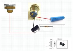
This should do it. The N fet is a neg switch that it triggered by the atty.
Just to make it stupid clear for I'm guessing it should be like this

Last edited:
BaDaBooM
Mod Maker
- Joined
- Nov 15, 2013
- Messages
- 650
After tinkering a bit this works, is much faster, easier and cheaper.
Solder the resistor to the switch led positive.
Solder the free end of the resistor to the positive lead.
Bridge the switch led negative with the sx board switch postive and the switch where it says 2A pole.
Solder the sx board switch negative to the free switch pole.
I tested it with a 15k resistor and the led light was dim should be much brighter with a 47ohm one.


Tested this way too today and works fine.
Hey guys,
I too am planning on wiring the same switch to a DNA board in the same way.
Would this diagram work with a DNA board? Same mosfet and resistors etc?
Similar threads
- Replies
- 2
- Views
- 398


