

jock1092
Achiever
- Joined
- Jun 7, 2016
- Messages
- 1,338
So two mods built tonight, thankfully they have broken my 3 build of death streak...
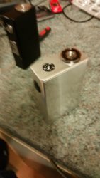
So first a black gboy+ remake of my unregulated parallel build since the old one had taken a fair beating and had some bad tool marks, though a slip of my file made a nasty scratch

Put a modmaker 510 on in place of my old fdv one because they are just better imo
Second is a first for me, a for working 555 pwm build using the breakout v3 pcb in a wideboy100
It was so much easier than the other pwm mods I've attempted but remains unfinished but working as the old fat daddy 510 found a temporary home with it ( will be replacing with a *hopefully* countersunk mm 510)
At this point TinyPic has gone wonky so no nice pics ( just attachments
And for @Bazz_74 a probably poor step by step of the board and a link to the wiring diagram
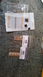
So my first pic is the parts,
pcb,
0.1 and 0.01 capacitors,
1k resistors
Diodes
N-channel mosfet
Fire switch
510
Dual 18650 sled
Enclosure
10kpotentiometer
555 timer plus the timer mount - the mount is optional but I picked it because of you break the mount you still have the timer that can attach in the same way, with the mount allowing an easy swap out if you break the timer some other way
16 and 24 gauge wire
Heatshrink
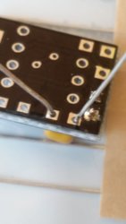
1 I started with the caps ( use the pic in modmaker for easy directions on what goes where here)
I bend the legs to fit the pcb, poke through and bend over leg to hold in place then solder
For reference C1 is the 0.1 cap and C2 is the 0.01
2 after the caps I did the resistor on the same way but with a bit more bending on the legs as it was a tight fit
Reference - 1k resistor on the R1 tabs
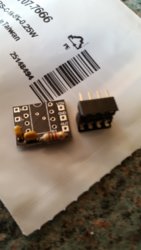
3 fit the mount by matching the groove at the top with the groove drawn on the pcb, same when attaching the timer
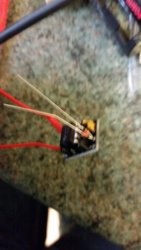
4 - Diodes you need two of these in one hole, I would go for soldering then both to a thin control wire like 22 gauge as it's a tight fit
They have a black end, make sure it one black end down and one up ( so they face opposite directions) and only connect together on the pcb side
These go in the legs hole
5 solder a control wire ( thin gauge) to the wiper tab
So first a black gboy+ remake of my unregulated parallel build since the old one had taken a fair beating and had some bad tool marks, though a slip of my file made a nasty scratch
Put a modmaker 510 on in place of my old fdv one because they are just better imo
Second is a first for me, a for working 555 pwm build using the breakout v3 pcb in a wideboy100
It was so much easier than the other pwm mods I've attempted but remains unfinished but working as the old fat daddy 510 found a temporary home with it ( will be replacing with a *hopefully* countersunk mm 510)
At this point TinyPic has gone wonky so no nice pics ( just attachments
And for @Bazz_74 a probably poor step by step of the board and a link to the wiring diagram
So my first pic is the parts,
pcb,
0.1 and 0.01 capacitors,
1k resistors
Diodes
N-channel mosfet
Fire switch
510
Dual 18650 sled
Enclosure
10kpotentiometer
555 timer plus the timer mount - the mount is optional but I picked it because of you break the mount you still have the timer that can attach in the same way, with the mount allowing an easy swap out if you break the timer some other way
16 and 24 gauge wire
Heatshrink
1 I started with the caps ( use the pic in modmaker for easy directions on what goes where here)
I bend the legs to fit the pcb, poke through and bend over leg to hold in place then solder
For reference C1 is the 0.1 cap and C2 is the 0.01
2 after the caps I did the resistor on the same way but with a bit more bending on the legs as it was a tight fit
Reference - 1k resistor on the R1 tabs
3 fit the mount by matching the groove at the top with the groove drawn on the pcb, same when attaching the timer
4 - Diodes you need two of these in one hole, I would go for soldering then both to a thin control wire like 22 gauge as it's a tight fit
They have a black end, make sure it one black end down and one up ( so they face opposite directions) and only connect together on the pcb side
These go in the legs hole
5 solder a control wire ( thin gauge) to the wiper tab
Attachments
Last edited: